
What are the steps for connecting industrial robot cables?--YM ROBOT
I. Connection Steps
1. Power Cable Connection
Determine the Connection Location
According to the robot layout diagram, locate the power module or driver to which the power cable should be connected. Typically, the power cable is connected to the power distribution unit or the power interface of the driver inside the robot's control cabinet.
Connect the Cable
Align the power cable plug with the interface and gently insert it, ensuring the plug is fully inserted. Some interfaces may require rotating the plug or pressing a locking device to secure the plug.
Use a screwdriver or wrench to tighten the fixing screws on the plug to prevent loosening. The tightening torque of the screws should comply with the manufacturer's requirements; overtightening may damage the screws or interface, while undertightening may lead to poor contact.
Label the Cable
Use cable labels to identify the power cable, indicating its purpose, starting point, and ending point, to facilitate subsequent maintenance and troubleshooting.
2. Signal Cable Connection
Distinguish Signal Types
Signal cables include control signal cables, sensor signal cables, etc. Before connecting, differentiate the types and functions of different signal cables to ensure correct connection. For example, control signal cables are used to transmit robot control commands, while sensor signal cables are used to transmit sensor detection signals.
Connect the Cable
Insert the signal cable plug into the corresponding interface according to the pin definition of the interface. Pay attention to the direction of the plug and the pin correspondence to avoid incorrect insertion.
For signal cables that require soldering, use professional soldering tools and solder, and perform soldering according to the soldering process requirements. After soldering, check whether the solder joints are firm and free from cold solder joints or short circuits.
Secure the Cable
Use cable ties to secure the signal cables to the robot's cable tray or rack to prevent the cables from loosening or rubbing against other components. The cable fixing spacing should be appropriate, generally every 20-30 centimeters.
3. Communication Cable Connection
Select the Communication Protocol
According to the robot's communication requirements, select the appropriate communication protocol and communication cable. Common communication protocols include Ethernet, Profibus, Profinet, etc. Different communication protocols require the use of corresponding communication cables and interfaces. Connecting Cables
Connect both ends of the communication cable to the communication interfaces of the robot controller and the external device (such as PLC, host computer, etc.). Ensure that the pins of the connectors are correctly aligned and the connection is secure.
For fiber optic communication cables, pay attention to the bending radius of the fiber to avoid excessive bending that could lead to signal attenuation or interruption.
Testing Communication
After connecting, use appropriate testing tools or software to test the communication line and ensure proper communication. For example, use the ping command to test network communication, or use a professional communication tester to check the quality of the communication signal.
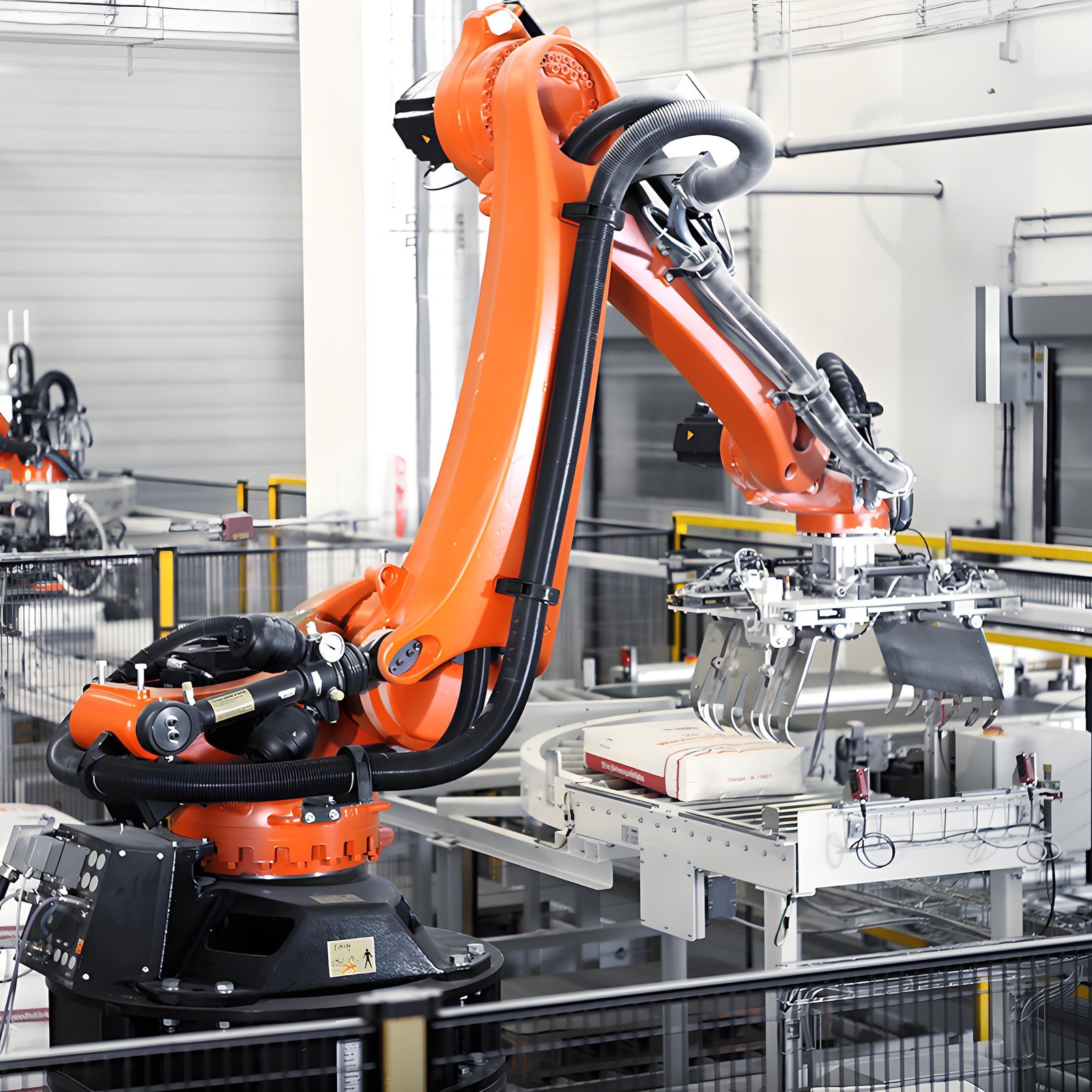
II. Post-Connection Inspection and Testing
Visual Inspection
Check that all cable connections are secure, plugs are firmly inserted, and cable ties are neatly fastened. Ensure that the cables are not loose, twisted, or tangled.
Electrical Testing
Use electrical testing tools such as a multimeter to perform insulation resistance and continuity tests on the power cables to ensure there are no short circuits, open circuits, or leakage.
Perform signal testing on signal and communication cables to check if signal transmission is normal and the waveform meets the requirements.
Functional Testing
Start the robot and perform simple motion and functional tests. Observe whether the robot's operation is normal and whether all sensors and actuators are working correctly. If any abnormalities are found, troubleshoot the cable connection problems immediately.
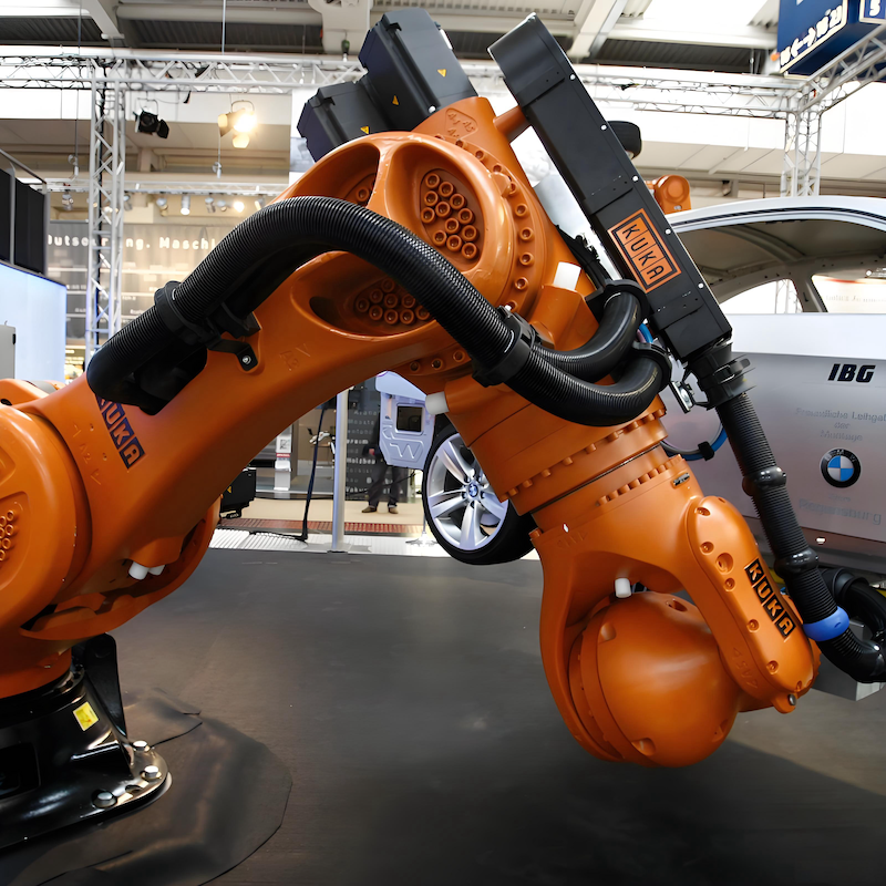
Contact us for more information about KUKA Robot
FANUC Robot|ABB Robot|KUKA Robot|YASKAWA Robot|KAWASAKI Robot|UR Cobot|JAKA Cobot|OTC Welding Robot|Positioner|Guide Rail|Robot accessories|Robot integration|Industrial robot|cobot|Scara robot|Delta Robot
 China Industrial Robot Supplie
 When Customers Ask for Differe
Why Fast Quotation Response Ma
How a One-Stop Industrial Robo
When Customers Ask for Differe
Why Fast Quotation Response Ma
How a One-Stop Industrial Robo